
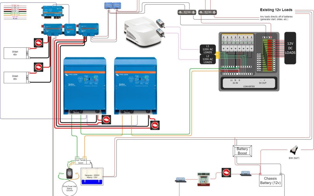
First thought: do NOT use green for power wires in your drawing! Blue, red, black, but not green as green universally denotes a ground connector. Neutral wires should be shown carefully too as they are typically white. OK, now that I’m done trashing your diagram…
Interesting setup! I’d add a small charger for the chassis batteries if you have not already planned for that. The detail in the drawing isn’t clear what those two lines off the chassis battery going to the (charge controller?) are for. I use a NOCO Genius 5 amp charger for my chassis batteries and it works very well.
Finally I’m not sure how long you could run the AC units on that setup. You’ll have to do the math there… You’re installing a rather big set of batteries, so how are they being charged?
I find your project very interesting!
A few other comments as a reply to your comment too.
(Sorry, I know just about no one is reading this blathering- it helps me to write it out and get it out of my head so I can refer to it later.)
I welcome any and all input. I just finished a draft of my wiring diagram to show me how all of these pieces come together.
Download PDF version – https://drive.google.com/file/d/14VF51P1hqGCt4lR-oD4DeelqB70Hl02q/view?usp=sharing
The gist of it is that the batteries are wired together using a Lynx Power In. This keeps the wiring tidy. This then hooks into the Lynx Shunt. Along side of that, most of the proper wiring and fusing are handled by the Lynx Distributor. The Cerbo is a piece that communicates the status out to the Victron apps and some kind of web portal for managing all of it; honestly, I’m not sure how that latter portion works.
Off of the distributor are a couple of things. First and foremost, the pair of Quattro 5000 watt inverter/chargers. After that, I have a pair of Orion 48v-to-12v step-down converters for feeding the existing 12v system. They’re paralleled together for a total of 60amps. I’ll need to see what the built-in converter puts out so that I’m supporting that.
Then there are a few other things- I would like to get some kind of battery bank charging while driving down the road, so I’ll be adding a Sterling 12-to-48v battery charger. (I’m realizing now that I’ve likely messed up by having the charging output from it go straight to the Power In, which will likely make it bypass the shunt.) I also need to ensure that this is ignition protected.
I then have a Battery Isolation Manager (BIM) that is supposed to cross-charge the house and chassis batteries. I haven’t yet decided if I’m keeping this or ditching it. If I keep it, my fixed output of the Orion 48v to 12v step-down converter should allow it to send a charge to the chassis batteries. I don’t need any kind of reverse charging.
And finally, a future Doug problem is how to start the generator. The start up load that it puts on the 12v system is intense and likely will exceed the capacity of the Orion step-down converters. There’s a “battery boost” button that essentially jumps the generator off of the chassis batteries. I’m hopeful that this will be enough to let me start the generator as needed. We’ll see, though.
Updated diagram based on various input.
PNG: https://i.imgur.com/C5lktSY.png
PDF: https://drive.google.com/file/d/1QGQZjiAviwbd5OyPTteMNvo1YVJ7vYG3/view?usp=sharing
Niiiiice. 600AH @ 12V is plenty big, at 48V it’s downright enormous.